
How Microduct Fiber Optic Cable Installation Quality Is Verified Before Network Handover
A fibre network can meet its design specifications on paper yet still underperform if installation defects go unnoticed before handover. Blocked pathways, excessive friction during cable blowing, unexpected optical loss, and incomplete route records can all create problems long after contractors have left the site.
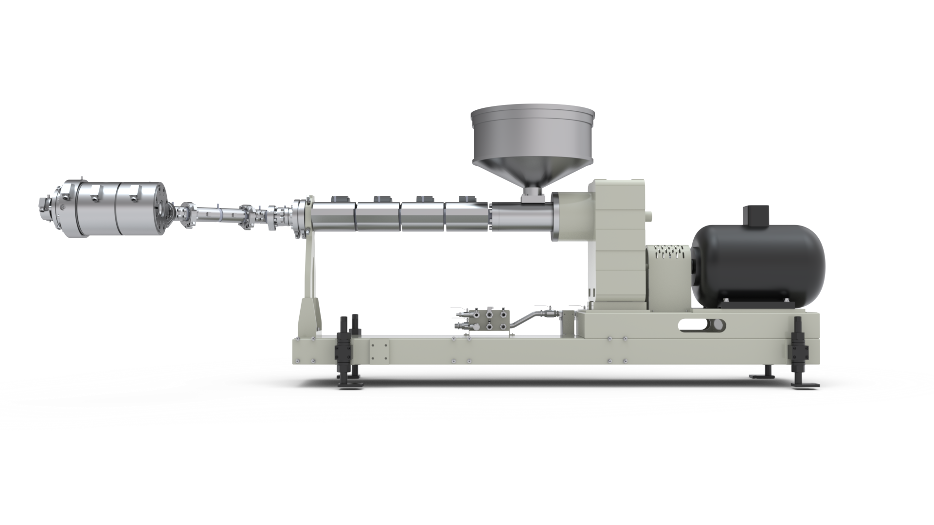
Verifying a microduct fiber optic cable installation requires more than confirming that cable has reached its destination; the duct infrastructure, optical performance, and supporting documentation must each be checked against defined acceptance criteria. DEKUMA operates in polymer extrusion technology, an area relevant to producing dimensionally consistent duct systems for fibre deployment.
Checking Duct Integrity Before Cable Installation
Pressure testing can reveal leaks, damaged joints, or poorly sealed connections in a duct route before optical cable is introduced. The test method should follow the duct manufacturer’s requirements and project specifications, including the permitted pressure, stabilisation period, and acceptable pressure variation. Temperature changes can affect readings, so results should be interpreted under controlled conditions rather than treating every pressure drop as evidence of a defect.
Internal cleanliness and pathway continuity deserve separate attention. Dust, moisture, construction debris, and crushed sections can obstruct cable movement or increase friction during installation. A visual inspection of accessible ends, combined with suitable mandrel or passage checks where specified, can help identify restrictions. Testing should cover the entire planned route, including intermediate chambers, bends, couplers, and transitions between different duct sections.
Joint quality is especially important in long runs containing numerous connections. Poorly seated couplers may leak under pressure, while misaligned joints can create internal edges that interfere with cable movement. Inspectors should compare installed components with approved drawings, record any repairs, and repeat the relevant checks after corrective work. A microduct route that passes its initial inspection provides a more reliable foundation for cable installation, although it still requires verification under the project’s full acceptance procedure.
Validating Cable Blowing Performance
Successful cable blowing depends on the interaction between duct geometry, cable properties, airflow, and installation equipment. The relationship between cable diameter and duct internal diameter affects clearance, while route length, bend radius, elevation changes, and joint alignment influence resistance to movement. A route that appears straightforward on a drawing may behave differently if field conditions introduce additional bends or unexpected deviations.
During installation, technicians should monitor the parameters required by the cable and equipment manufacturers. These may include air pressure, airflow, feed speed, and the force applied to the cable. Excessive force or unsuitable operating conditions can damage the cable sheath or strain the optical fibres. If progress slows sharply or the equipment reaches a specified limit, the correct response is to investigate the cause rather than simply increase pressure or pushing force.
Blowing performance records help distinguish a successful installation from one that only appears successful because the cable reached the endpoint. Useful entries include the duct route identifier, cable type, installed length, equipment settings, completion time, and any interruptions or abnormal resistance. The final acceptance review should confirm that the installation method remained within approved limits. For a microduct fiber optic cable project, these records also provide a baseline if future faults suggest that a particular route experienced unusual installation resistance.
Measuring Optical Performance and Investigating Loss
Optical testing determines whether the installed fibre meets the required transmission performance. An optical loss test measures attenuation across the link, while an optical time-domain reflectometer (OTDR) can help locate events such as splices, connectors, bends, or breaks along the fibre. The two methods provide different information and may be required together under the project specification.
Reliable measurements depend on the correct test setup. Inspecting and cleaning connector end faces, using suitable reference cords, selecting the correct wavelength, and following an established reference method reduce avoidable measurement errors. Test results should be compared with the link loss budget, which accounts for the expected attenuation of fibre, connectors, splices, and other optical components. Acceptance limits should come from the approved design and applicable standards, not an improvised threshold applied after installation.
Unexpected loss requires investigation before handover. A high-loss event may result from a contaminated connector, excessive bending, a poor splice, or physical damage sustained during pulling or blowing. OTDR traces can help identify the location and character of a suspected fault, while end-to-end loss measurements confirm overall link performance. Each test should be associated with the correct fibre and route identifiers so that a passing result cannot accidentally be assigned to the wrong connection.
Compiling Handover Records for Long-Term Management
A useful handover package connects field installation details with the final network configuration. As-built drawings should show actual duct routes, chamber locations, cable paths, splice points, and relevant deviations from the original design. Route identifiers need to remain consistent across drawings, installation logs, test reports, and asset records; inconsistent naming can make future maintenance unnecessarily difficult.
The documentation should also preserve evidence of quality checks. Pressure-test results, cable-blowing records, optical loss measurements, OTDR traces, repair notes, and inspection sign-offs provide different pieces of the installation history. Each record should include enough information to identify the tested section, equipment or method used, date, result, and responsible party.
Conclusion
Network handover is the point at which installation work becomes a documented, maintainable asset. Reliable acceptance combines duct integrity checks, monitored cable installation, optical measurements, and records that connect every result to the correct route and fibre.=
A microduct fiber optic cable system should not be judged solely by whether the cable reaches its destination; its performance and installation history must also be verifiable. DEKUMA contributes to the manufacturing side through its focus on microduct extrusion stability and dimensional accuracy, while disciplined field testing and complete handover records provide the evidence needed for long-term network management.


